
课程明细
Circuits Analysis
- 星期一,第 3—4 节,1—16 周,南校区博学楼 1J1B403;教学班:C电气251、C电气252。
- 星期三,第 1—2 节,1—16 周,南校区博学楼 1J1D317;教学班:C电气251、C电气252。
电工电子学A
- 星期一,第 5—6 节,1—12 周,南校区博学楼 1J1D410;教学班:C机制253、C机制254。
- 星期三,第 9—10 节,1—12 周,南校区博学楼 1J1C305;教学班:C机制253、C机制254。
- 星期五,第 5—6 节,1—12 周,南校区博学楼 1J1D410;教学班:C机制253、C机制254。
补充知识
- 什么是电阻: https://zhidao.baidu.com/daily/view?id=183681
- 电阻应用浅析: https://www.eet-china.com/mp/a416198.html
- 集总参数电路和分布参数电路: https://www.zhihu.com/question/320087308
作业
第一章作业
第1题
The charge flowing in a wire is plotted in Fig. 1.21. Sketch the corresponding current.
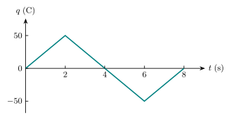
Fig. 1.21 — Charge waveform
第2题
The current entering the positive terminal of a device is $i(t)=3e^{-2t}\,\mathrm A$, and the voltage across the device is $v(t)=5\,di/dt\,\mathrm V$.
-
Find the charge delivered to the device between $t=0$ and $t=2\,\mathrm s$.
-
Calculate the power absorbed.
-
Determine the energy absorbed in 3 s.
第3题
Find the power absorbed by each of the elements in Fig. 1.26.
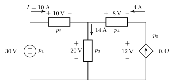
Fig. 1.26 — Element power (Problem 1.15)
第二章作业
第1题
Find the hot resistance of a lightbulb rated 60 W, 120 V.
第2题
Determine the number of branches and nodes in the circuit.
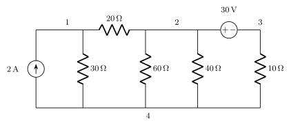
Branches and nodes
第3题
Calculate the power dissipated in the $5\,\Omega$ resistor in the circuit of Fig. 2.82.
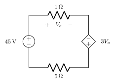
Fig. 2.82 — Problem 2.18
第4题
Find $V_o$ in the circuit in Fig. 2.83 and the power dissipated by the controlled source.
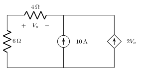
Fig. 2.83 — Problem 2.19
第5题
Find the equivalent resistance at terminals $a$-$b$ for each of the networks in Fig. 2.99.
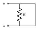
Fig. 2.99(a)
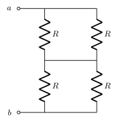
Fig. 2.99(b)
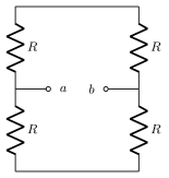
Fig. 2.99(c)
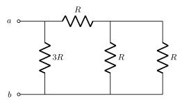
Fig. 2.99(d)
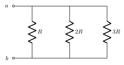
Fig. 2.99(e)
第6题
As a design engineer, you are asked to design a lighting system consisting of a 70-W power supply and two lightbulbs as shown in Fig. 2.118. You must select the two bulbs from the following three available bulbs.
- $R_1=80\,\Omega$, cost = $0.60 (standard size)
- $R_2=90\,\Omega$, cost = $0.90 (standard size)
- $R_3=100\,\Omega$, cost = $0.75 (nonstandard size)
The system should be designed for minimum cost such that $I=1.2\,\mathrm A\pm5\%$.
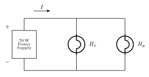
Fig. 2.118 — 70-W power supply and two lamps
第三章作业
第1题
For the circuit in Fig. 3.51, obtain $v_1$ and $v_2$.
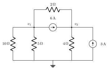
Fig. 3.51
第2题
For the circuit in Fig. 3.66, find $v_1$ and $v_2$ using nodal analysis.
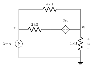
Fig. 3.66
第3题
For the bridge network in Fig. 3.76, find $i_o$ using mesh analysis.
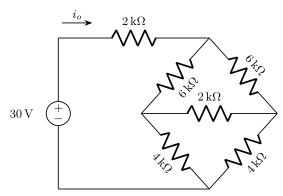
Fig. 3.76
第4题
Find $v_x$ and $i_x$ in the circuit shown in Fig. 3.91.
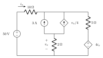
Fig. 3.91
第四章作业
第1题
For the circuit in Fig. 4.73, assume $v_o=1\,\mathrm V$, and use linearity to find the actual value of $v_o$.
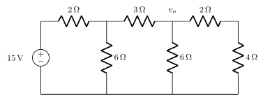
Fig. 4.73
第2题
Given the circuit in Fig. 4.75, calculate $i_x$ and the power dissipated by the $10\,\Omega$ resistor using superposition.
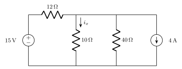
Fig. 4.75
第3题
Find $v_x$ in Fig. 4.83 by superposition.
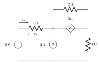
Fig. 4.83
第4题
Obtain $v_o$ in the circuit of Fig. 4.87 using source transformation. Check your result using PSpice.
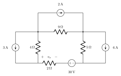
Fig. 4.87
第5题
Find the Thevenin equivalent at terminals $a$-$b$ of the circuit in Fig. 4.93.
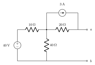
Fig. 4.93
第6题
Determine the Thevenin and Norton equivalents at terminals $a$-$b$ of the circuit in Fig. 4.107.
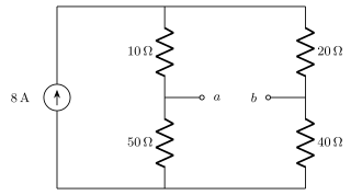
Fig. 4.107
第7题
For the circuit in Fig. 4.117, what resistor connected across terminals $a$-$b$ will absorb maximum power from the circuit? What is that power?
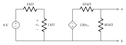
Fig. 4.117
第六章作业
第1题
The voltage waveform in Fig. 6.46 is applied across a $30\,\mu\mathrm F$ capacitor. Draw the current waveform through it.
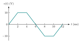
Fig. 6.46 — Capacitor voltage waveform
第2题
Find the voltage across the capacitors in the circuit of Fig. 6.49 under dc conditions.
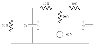
Fig. 6.49
第3题
Determine the equivalent capacitance for each of the circuits in Fig. 6.51.
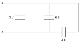
Fig. 6.51(a)
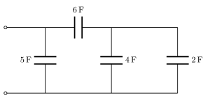
Fig. 6.51(b)
第4题
The current through a $5\,\mathrm{mH}$ inductor is shown in Fig. 6.66. Determine the voltage across the inductor at $t=1,3,\text{ and }5\,\mathrm{ms}$.
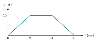
Fig. 6.66 — Inductor current waveform
第5题
Under DC conditions, find energy and voltage of capacitor and inductor.
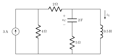
Capacitor and inductor under DC conditions
第6题
Find $L_{\mathrm{eq}}$ at the terminals of the circuit in Fig. 6.75.
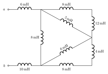
Fig. 6.75
第七章作业
第1题
The switch in Fig. 7.84 moves instantaneously from $A$ to $B$ at $t=0$. Find $v$ for $t>0$.
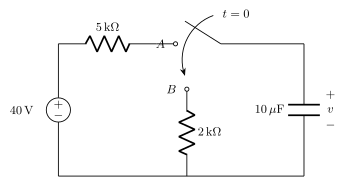
Fig. 7.84
第2题
The switch in Fig. 7.86 has been closed for a long time, and it opens at $t=0$. Find $v(t)$ for $t\ge0$.
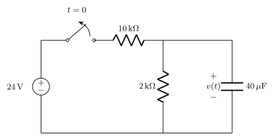
Fig. 7.86
第3题
In the circuit of Fig. 7.93, $$v(t)=20e^{-10^3t}\,\mathrm V,\qquad t>0,$$ $$i(t)=4e^{-10^3t}\,\mathrm{mA},\qquad t>0.$$
-
Find $R$, $L$, and $\tau$.
-
Calculate the energy dissipated in the resistance for $0\lt t\lt0.5\,\mathrm{ms}$.
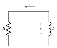
Fig. 7.93
第4题
Find $i(t)$ and $v(t)$ for $t>0$ in the circuit of Fig. 7.102 if $i(0)=10\,\mathrm A$.
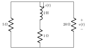
Fig. 7.102
第5题
In the circuit of Fig. 7.99, find $i(t)$ for $t>0$ if $i(0)=2\,\mathrm A$.
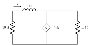
Fig. 7.99
第九章作业
第1题
For the following pairs of sinusoids, determine which one leads and by how much.
-
$v(t)=10\cos(4t-60^\circ)$ and $i(t)=4\sin(4t+50^\circ)$.
-
$v_1(t)=4\cos(377t+10^\circ)$ and $v_2(t)=-20\cos377t$.
-
$x(t)=13\cos2t+5\sin2t$ and $y(t)=15\cos(2t-11.8^\circ)$.
第2题
Using phasors, find:
-
$3\cos(20t+10^\circ)-5\cos(20t-30^\circ)$
-
$40\sin50t+30\cos(50t-45^\circ)$
-
$20\sin400t+10\cos(400t+60^\circ)-5\sin(400t-20^\circ)$
第3题
Using phasors, determine $i(t)$ in the following equations:
-
$2\dfrac{di}{dt}+3i(t)=4\cos(2t-45^\circ)$
-
$10\int i\,dt+\dfrac{di}{dt}+6i(t)=5\cos(5t+22^\circ)$
第4题
Find current $i$ in the circuit of Fig. 9.42, when $v_s(t)=50\cos200t\,\mathrm V$.
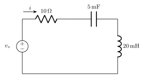
Fig. 9.42
第5题
Find current $I_o$ in the circuit shown in Fig. 9.50.
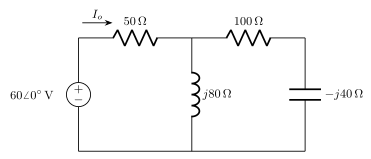
Fig. 9.50
第6题
At $\omega=10^3\,\mathrm{rad/s}$, find the input admittance of each of the circuits in Fig. 9.74.
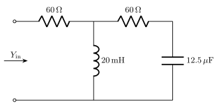
Fig. 9.74(a)
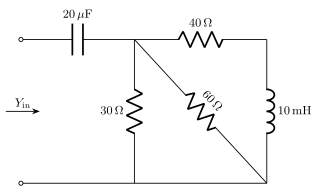
Fig. 9.74(b)
第十章作业
第1题
Determine $i$ in the circuit of Fig. 10.50.
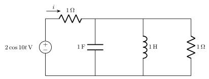
Fig. 10.50
第2题
Determine $V_x$ in Fig. 10.55.
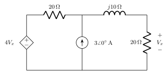
Fig. 10.55
第3题
Solve for $i_o$ in Fig. 10.73 using mesh analysis.
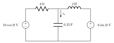
Fig. 10.73 — Problem 10.25
第4题
Find $i_o$ in the circuit shown in Fig. 10.85 using superposition.
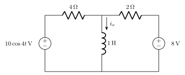
Fig. 10.85 — Problem 10.40
第5题
Using source transformation, find $i$ in the circuit of Fig. 10.94.
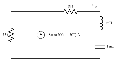
Fig. 10.94 — Problem 10.49
第6题
For each of the circuits in Fig. 10.99, obtain Thevenin and Norton equivalent circuits at terminals $a$-$b$.
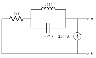
Fig. 10.99(a)

Fig. 10.99(b) — Problem 10.56
第十一章作业
第1题
Given the circuit in Fig. 11.35, find the average power supplied or absorbed by each element.
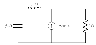
Fig. 11.35
第2题
In the circuit of Fig. 11.46, find the value of $Z_L$ that will absorb the maximum power and the value of the maximum power.
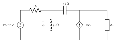
Fig. 11.46
第3题
For the power system in Fig. 11.67, find: (a) the average power, (b) the reactive power, (c) the power factor. Note that 220 V is an rms value.
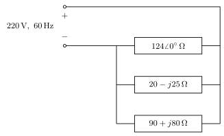
Fig. 11.67
第4题
For the entire circuit in Fig. 11.70, calculate:
-
The power factor
-
The average power delivered by the source
-
The reactive power
-
The apparent power
-
The complex power
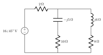
Fig. 11.70
第十二章作业
第1题
Obtain the line currents in the three-phase circuit of Fig. 12.42.
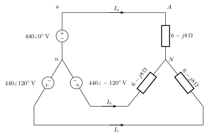
Fig. 12.42 — Three-phase Y–Y circuit
第2题
In the balanced three-phase Y–$\Delta$ system in Fig. 12.46, find the line current $I_L$ and the average power delivered to the load.
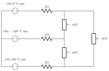
Fig. 12.46 — Problem 12.13
第3题
In Fig. 12.56, the rms value of the line voltage is 208 V. Find the average power delivered to the load.
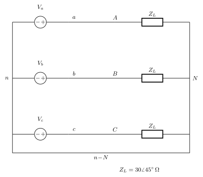
Fig. 12.56 — Three-phase Y–Y circuit
第4题
Consider the $\Delta$–$\Delta$ system shown in Fig. 12.60. Take $Z_1=8+j6\,\Omega$, $Z_2=4.2-j2.2\,\Omega$, and $Z_3=10+j0\,\Omega$.
-
Find the phase currents $I_{AB}$, $I_{BC}$, and $I_{CA}$.
-
Calculate line currents $I_{aA}$, $I_{bB}$, and $I_{cC}$.
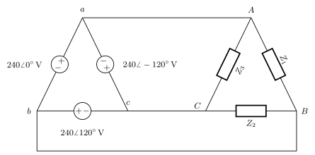
Fig. 12.60 — Chapter 12, Problem 51
第十三章作业 · Magnetically Coupled Circuits
Problem 13.1
For the three coupled coils in Fig. 13.72, calculate the total inductance.
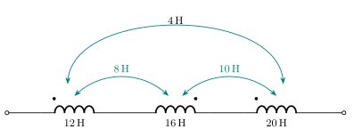
Fig. 13.72 — Problem 13.1
Problem 13.4
(a) For the coupled coils in Fig. 13.74(a), show that $$L_{\mathrm{eq}}=L_1+L_2+2M.$$
(b) For the coupled coils in Fig. 13.74(b), show that $$L_{\mathrm{eq}}=\frac{L_1L_2-M^2}{L_1+L_2-2M}.$$
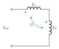
Fig. 13.74(a) — Problem 13.4
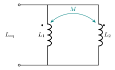
Fig. 13.74(b) — Problem 13.4
Problem 13.8
Find $v(t)$ for the circuit in Fig. 13.77.
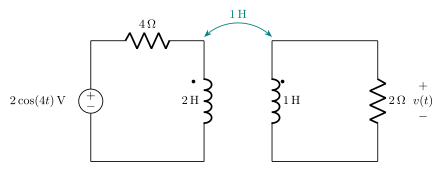
Fig. 13.77 — Problem 13.8
Problem 13.10
Find $v_o$ in the circuit of Fig. 13.79.
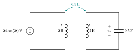
Fig. 13.79 — Problem 13.10
Problem 13.15
Find the Norton equivalent for the circuit in Fig. 13.84 at terminals $a$-$b$.
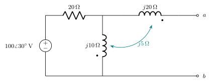
Fig. 13.84 — Problem 13.15
Problem 13.36
As done in Fig. 13.32, obtain the relationships between terminal voltages and currents for each of the ideal transformers in Fig. 13.105.
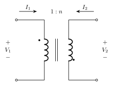
Fig. 13.105(a) — Problem 13.36
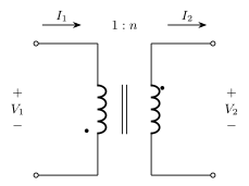
Fig. 13.105(b) — Problem 13.36
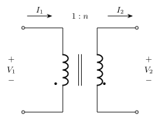
Fig. 13.105(c) — Problem 13.36
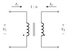
Fig. 13.105(d) — Problem 13.36
Problem 13.41
Determine $I_1$ and $I_2$ in the circuit of Fig. 13.106.
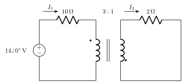
Fig. 13.106 — Problem 13.41
Problem 13.45
For the circuit shown in Fig. 13.110, find the value of the average power absorbed by the $8\,\Omega$ resistor.
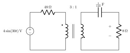
Fig. 13.110 — Problem 13.45
还没有可见的评论。